Two Labels, One SRH, and One Very Annoying rp_filter: How a Linux Network Made It from IP to SRv6 L3VPN
Spoiler: this is not about stuffing more words like
mpls,segment-routing, andsrv6into a config. It is about stopping after every one of those words and asking: where did the packet actually go?
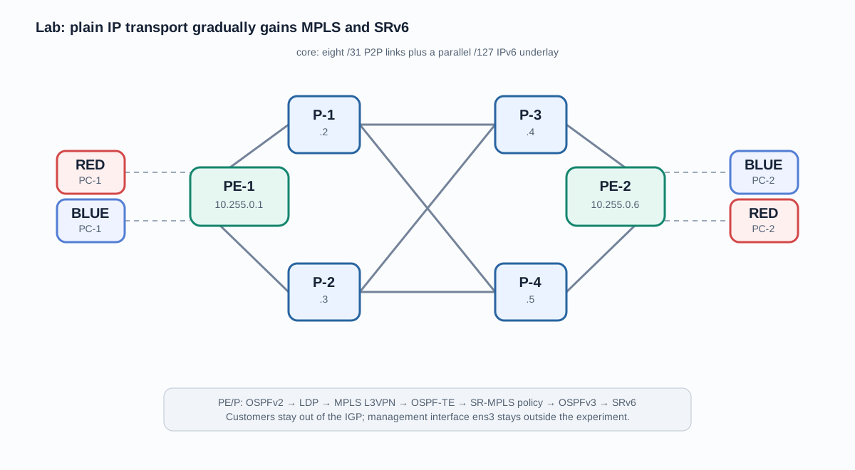
We had ten Linux machines connected by virtual links, plus a separate management network. At the beginning, this was not an “MPLS lab”: there was no IPv4 data plane, FRR was missing on some nodes, and the neighbors shared little more than interfaces and a healthy amount of mutual suspicion.
The goal was fairly ambitious: start with bare point-to-point links, build isolated L3VPNs, steer traffic with SR-MPLS, and finally get one service running as an actual SRv6 L3VPN. Not draw a perfect diagram after the fact, but build the layers one by one and verify what each layer was really doing.
This is the story of that experiment. There will be commands and pieces of the FIB, but no mile-long configuration dumps. In this story, a configuration does not count as an achievement until protocol state or a packet on the wire backs it up.
The Zoo We Started With
The core consists of two PEs and four P routers. The PEs are connected by two diamond-shaped paths through P-1/P-3 and P-2/P-4, plus two cross-links. Each edge has two customers, RED and BLUE. The management interface, ens3, lives separately and was deliberately left alone. Losing SSH for the sake of a beautiful netplan apply makes for educational content of the wrong kind.
The data links received addresses from 10.10.0.0/27, one /31 per point-to-point link:
| Link | Addresses |
|---|---|
| PE-1 — P-1 | 10.10.0.0/31 — 10.10.0.1/31 |
| PE-1 — P-2 | 10.10.0.2/31 — 10.10.0.3/31 |
| P-1 — P-3 | 10.10.0.4/31 — 10.10.0.5/31 |
| P-1 — P-4 | 10.10.0.6/31 — 10.10.0.7/31 |
| P-2 — P-3 | 10.10.0.8/31 — 10.10.0.9/31 |
| P-2 — P-4 | 10.10.0.10/31 — 10.10.0.11/31 |
| P-3 — PE-2 | 10.10.0.12/31 — 10.10.0.13/31 |
| P-4 — PE-2 | 10.10.0.14/31 — 10.10.0.15/31 |
The four customer-facing links received the remaining /31s. We enabled net.ipv4.ip_forward=1 on the P and PE nodes, but not on the PCs. They are customers here, not routers that simply have not yet been given enough power.
Before moving on, we tested every link in two ways: ip route get had to select the expected interface, and two ICMP echo requests had to receive two replies. For example:
# PE-1 → P-1
10.10.0.1 dev ens4 src 10.10.0.0
2 packets transmitted, 2 received, 0% packet loss

# P-2 → P-3
10.10.0.9 dev ens6 src 10.10.0.8
2 packets transmitted, 2 received, 0% packet loss
Remote addresses were unreachable at this point, and that was fine. Every node had only connected routes. This is a useful boundary to recognize: no route between the PEs before an IGP is not a bug to be wallpapered over with MPLS. It is the honest limit of the first layer.
First, Let’s Teach IP to Go Places
We assigned stable loopbacks and router IDs for OSPFv2:
| Node | Loopback | Node SID later |
|---|---|---|
| PE-1 | 10.255.0.1/32 |
16001 |
| P-1 | 10.255.0.2/32 |
16002 |
| P-2 | 10.255.0.3/32 |
16003 |
| P-3 | 10.255.0.4/32 |
16004 |
| P-4 | 10.255.0.5/32 |
16005 |
| PE-2 | 10.255.0.6/32 |
16006 |
A systemd unit brings up the loopback before FRR starts. A router ID should not suddenly depend on how a physical port happens to feel today. We installed FRR 8.4.4 with ospfd on the P and PE nodes, placed all core interfaces in area 0 as point-to-point links, and configured passive-interface default. Customer-facing ports and loopbacks have no business sending OSPF Hellos into the void.
We expected 16 directional adjacencies: two on each PE and three on each P router. That is exactly how many Full/- states appeared. On PE-1, the route to PE-2’s loopback arrived over two equal-cost paths:
O>* 10.255.0.6/32 [110/3] via 10.10.0.1, ens4
  *                       via 10.10.0.3, ens5
A pretty show ip route was not enough; we also wanted the kernel FIB. It selected one ECMP next hop, and the loopback-to-loopback ping returned without loss:
$ ip route get 10.255.0.6 from 10.255.0.1
10.255.0.6 from 10.255.0.1 via 10.10.0.3 dev ens5

$ ping -I 10.255.0.1 -c 4 10.255.0.6
4 packets transmitted, 4 received, 0% packet loss
The reply TTL was 62, so the packet really did cross two transit P routers. Only now did the later protocols have a proper transport foundation.
Add MPLS, but Not a Service Yet
We did not need LDP merely because “MPLS must be enabled.” IP delivery to the loopbacks already worked, so we could add a second forwarding mechanism: the ingress pushes a label for a FEC, and a transit P router decides what to do with the top label.
On all six P/PE nodes, we loaded mpls_router, enabled MPLS input only on core interfaces, set net.mpls.platform_labels=1048575, and started ldpd. Three machines did not have the module in their installed package set, so we added the linux-modules-extra package matching the running kernel, without a reboot. MPLS remained disabled on access ports. Customers have absolutely no reason to accept labeled packets.
The first attempt taught us something. We added the LDP block directly to /etc/frr/frr.conf; the daemon started, but show mpls ldp ipv4 interface showed no interfaces at all. The configuration existed, yet working LDP state did not. We applied the sections through vtysh, explicitly leaving each nested mode, and saved with write memory. The ports then became ACTIVE and the neighbors OPERATIONAL.
We used PE-2’s loopback as the FEC. On PE-1, LDP allocated local label 23 and received remote label 22 from both next hops:
show mpls ldp ipv4 binding 10.255.0.6/32
ipv4 10.255.0.6/32 10.255.0.2  Local 23  Remote 22  in use yes
ipv4 10.255.0.6/32 10.255.0.3  Local 23  Remote 22  in use yes

ip route get 10.255.0.6 from 10.255.0.1
10.255.0.6 from 10.255.0.1 encap mpls 22 via 10.10.0.3 dev ens5
P-2 swapped incoming label 22 for 25. A capture on its ens4 during ICMP caught the most convincing argument available:
ethertype MPLS unicast (0x8847)
  MPLS (label 22, tc 0, [S], ttl 64)
  10.255.0.1 > 10.255.0.6: ICMP echo request
In other words, LDP distributed labels, the kernel installed them, the PE really pushed one, and the P router really received MPLS. Celebration is allowed, but only a small one: this is MPLS transport, not a customer service yet.
Two VPNs, Two Labels, and a Core That Couldn’t Care Less
Next, we built two isolated services:
| VPN | Left network | Right network | RT |
|---|---|---|---|
| RED | 10.10.0.16/31 |
10.10.0.22/31 |
65000:100 |
| BLUE | 10.10.0.18/31 |
10.10.0.20/31 |
65000:200 |
Both PEs received Linux VRFs: RED with table 1001 and BLUE with table 1002. We moved the access interfaces into their VRFs. Netplan on the PEs manages only core addresses, while an idempotent systemd unit creates the VRFs and customer-edge addresses before FRR starts. Otherwise, after a reboot, netplan will dutifully return the CE address to the default VRF, and the lab will become very educational again—just not in a pleasant way.
MP-BGP between the PE loopbacks in AS 65000 carries VPNv4 and extended communities. Each PE has a unique RD, while the RT is shared per color. The distinction matters: the RD makes the NLRI unique; the RT decides which VRF is allowed to import the route.
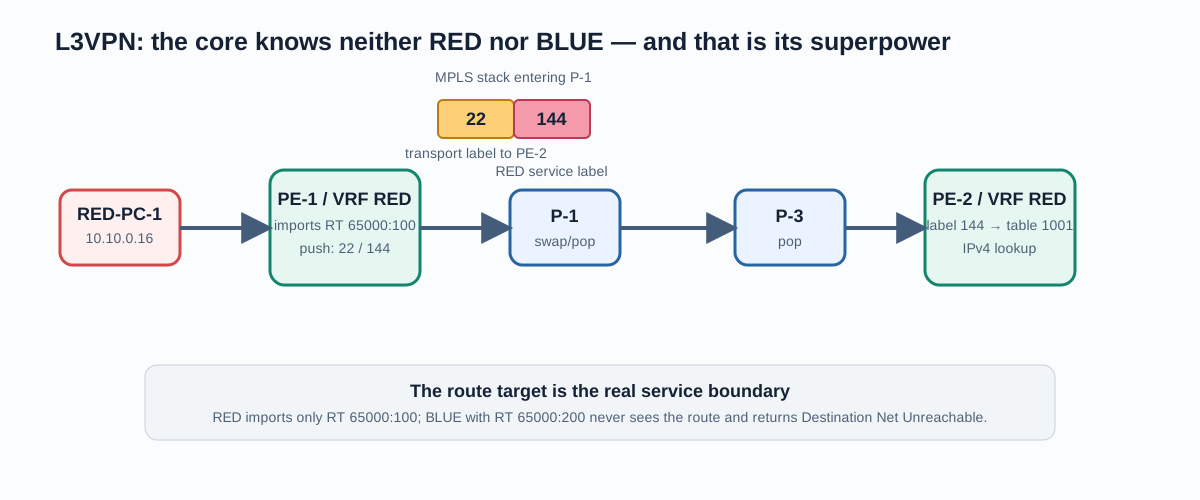
After export and import, PE-1’s kernel FIB showed exactly what we wanted:
ip route get 10.10.0.22 vrf RED
10.10.0.22 encap mpls 22/144 via 10.10.0.1 dev ens4 table 1001

ip route get 10.10.0.20 vrf BLUE
10.10.0.20 encap mpls 22/145 via 10.10.0.3 dev ens5 table 1002
The top label delivers the packet to the egress PE; the bottom label selects the service there. RED customer-to-customer ping worked, and a capture on P-1 showed stack 22/144 with IPv4 inside. BLUE did the same with its own service label. Just as importantly, RED-to-BLUE and BLUE-to-RED received Destination Net Unreachable from the local PE. The foreign RT was not imported; the packet did not merely “get lost somewhere in the core.”
There was also a small lesson in recovery order. Enabling BGP restarted FRR on a PE. OSPF quickly returned to Full, but one PE-2 LDP neighbor remained in SYN-SENT. Discovery worked, IP ping between transport addresses worked, and the log explained the rest: LDP had started before OSPF restored the route and got Network is unreachable. Running clear mpls ldp neighbor after the IP path was ready brought the adjacency up. The VPN was innocent. If a lower layer is still reassembling itself, editing BGP will not help.
Traffic Engineering: Data Is Not a Path
When plain OSPF sees equal paths, it spreads traffic with ECMP. It does not know that an important service should use P-1/P-3, that the alternate path has little capacity left, or that part of the network is under maintenance.
We added a TE information plane to OSPF: mpls-te on, router address, export, and link parameters. The lab model was explicit rather than pretending that a virtual interface’s bandwidth was trustworthy telemetry:
| Corridor | TE metric | Unreserved BW | Role in the model |
|---|---|---|---|
| PE-1 — P-1 — P-3 — PE-2 | 10 | 100 MB/s | preferred / gold |
| PE-1 — P-2 — P-4 — PE-2 | 20 | 25 MB/s | little capacity left |
| Cross-links P-1—P-4, P-2—P-3 | 50 | 50 MB/s | backup |
At first, link parameters were visible locally, but there were no TE LSAs in the LSDB. show ip ospf revealed the key line: OpaqueCapability flag is disabled. After enabling opaque capability on every P/PE node, PE-1 saw 16 area-local opaque LSAs—one for each direction of every core link. For example:
Opaque-Type 1 (Traffic Engineering LSA)
Advertising Router: 10.255.0.2
Traffic Engineering Metric: 10
Maximum Reservable Bandwidth: 1e+08 (Bytes/sec)
Unreserved Bandwidth [0..7]: 1e+08 (Bytes/sec)
FRR also refused a max-bw smaller than the already known interface maximum. Fair enough: a maximum cannot be lower than its related bandwidth fields. We kept FRR’s actual maximum and represented the lab’s available capacity through max-rsv-bw and unrsv-bw.
After all that, the regular route to PE-2 remained ECMP, and neither LDP nor L3VPN broke. That is the correct outcome. A TED is input for CSPF or a controller, not a spell that reroutes ICMP by itself. FRR 8.4.4 has no rsvpd and no complete RSVP-TE control plane with CSPF, reservation, and TE LSPs; calling this stage “working RSVP-TE” would have been fiction. The TE LSAs did genuinely propagate, though, which gave us a proven foundation for the next step.
When a Transport Label Becomes a Segment
Segment Routing solves a different part of the TE problem: the ingress puts instructions into the stack, while transit nodes execute shared SIDs instead of storing per-policy state for every LSP. With our SRGB of 16000–23999, the Node SIDs match the loopback table above. For example, [16002 | 16004 | 16006] means: go to P-1, then P-3, then PE-2.
We enabled OSPF SR-MPLS with Node MSD 8 on every P/PE node. On PE-1, it became something very concrete in the FIB:
ip -f mpls route show 16006
16006 proto ospf
  nexthop as to 16006 via inet 10.10.0.1 dev ens4
  nexthop as to 16006 via inet 10.10.0.3 dev ens5

ip route get 10.255.0.6 from 10.255.0.1
10.255.0.6 encap mpls 16006 via 10.10.0.3 dev ens5
A capture on P-2 caught MPLS label 16006 with the same ICMP packet inside. For L3VPN, only the top transport label changed: 16006/144 for RED and 16006/145 for BLUE. The service label—and therefore VRF isolation—remained intact. We deliberately left LDP neighbors enabled: the mechanisms coexist, but the FIB now prefers SR for these FECs.
There is no need to cast RSVP-TE and SR-MPLS as hero and villain. RSVP provides signaling and reservation when configured to do so; SR carries the path in a segment list and scales policy state more cleanly across transit nodes. SR does not measure congestion or reserve bandwidth by itself. Both approaches still need a sensible source of topology and constraints.
SR Policy: Now the Path Is Actually Chosen
A single Node SID for PE-2 still allows ECMP: the packet may leave through P-1 or P-2. We therefore enabled pathd on PE-1 and created a local explicit SR policy. No external PCE and no imaginary magic controller—just one segment list we could verify:
16002 → 16004 → 16006
 P-1     P-3     PE-2
The policy received color 100, endpoint 10.255.0.6, and binding SID 24000. pathd selected the candidate path, and Zebra installed it in the data plane. The BSID expanded immediately into 16004/16006 through P-1: the first segment already matched the directly connected next hop. That is an optimization, not P-1 mysteriously disappearing.
To make the policy more than a museum exhibit, an inbound BGP route map set sr-te color 100 on VPNv4 routes from PE-2. In this small lab, that affected both imported services. In a real network, steering should be narrowed by RT, community, or prefix. “Everything going to PE-2” is rarely a sound product requirement.
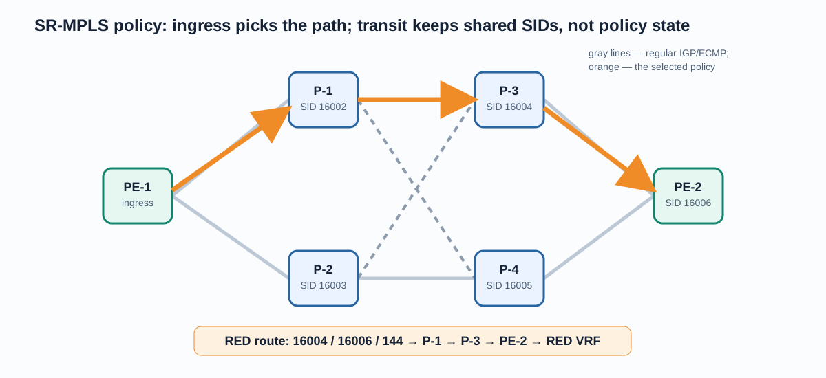
The RED FIB on PE-1 changed from:
10.10.0.22 encap mpls 16006/144 ...
to:
10.10.0.22 encap mpls 16004/16006/144 via 10.10.0.1 dev ens4 table 1001
A capture at P-1’s ingress showed that exact stack. P-1’s LFIB sent the remaining labels toward P-3 for SID 16004, and P-3’s LFIB sent SID 16006 toward PE-2. At last, we could say “explicit path” without hand-waving: we had the label list and forwarding behavior on every relevant transit node.
SRv6: Same Intent, Different Data Plane
SR-MPLS worked in this lab. We did not add SRv6 because MPLS had somehow “become obsolete.” SRv6 is interesting when the transport is already IPv6 and we want to express a path and a network function as IPv6 SIDs. The price is IPv6 plus SRH overhead, MTU planning, and a more complex operational model.
First, we built a parallel IPv6 underlay: /127s from fd10:10:0:x::/127 on the eight core links, OSPFv3, and locator prefixes. Before introducing an SRH, we verified ordinary IPv6 routing and ping to PE-2’s locator. Otherwise, troubleshooting would become a soup of OSPFv3, IPv6, and seg6 problems all at once.
For the manual experiment, we used:
| Node | SID | Behavior |
|---|---|---|
| P-1 | fd10:6:0:2:1::/128 |
End |
| P-3 | fd10:6:0:4:1::/128 |
End |
| PE-2 | fd10:6:0:6:100::/128 |
End.DT4 vrftable 1001 |
The ingress RED VRF received an IPv4 route with encap seg6. On the egress, a policy rule catches the locator in table 200, which contains seg6local End.DT4. We enabled seg6_enabled=1 only on data interfaces; Linux does not accept SRHs by default just because we asked nicely.
We captured real IPv6+SRH on P-1 and then on PE-2, with the inner IPv4 echo request intact. OSPFv3, locator reachability, and SRv6 encapsulation were therefore working. Yet RED-PC-2 received nothing. We could have called stage eight “SRv6 L3VPN complete” and blamed the rest on the weather. But the packet never reached the access VRF, so it was not complete.
“The Kernel Can’t Do It” Was Far Too Convenient
We first ran the official Linux self-test srv6_end_dt4_l3vpn_test.sh on PE-2 inside disposable namespaces. It passed all 18 tests. The kernel could do End.DT4; the difference between the self-test and the live lab was where we had to look.
The culprit was reverse-path filtering. After End.DT4, the inner IPv4 packet has source 10.10.0.16, but appears from the core context. Its reverse route lives in the RED VRF, not the global IPv4 table. With rp_filter=2, the lookup did not see the VRF route and dropped the packet before it reached the access interface:
ip route get 10.10.0.16 from 10.10.0.14 iif ens5
RTNETLINK answers: Network is unreachable
The upstream self-test disables RPF before creating the VRF. We made the narrowest change the lab required: rp_filter=0 on RED, the core interfaces, and the RED access interface, while management ens3 kept rp_filter=2. This is not a recommendation to “turn RPF off everywhere.” In production, source validation and policy routing must be designed together with the service data plane. Here, it was a specific interaction between Linux SRv6 End.DT4 and a VRF.
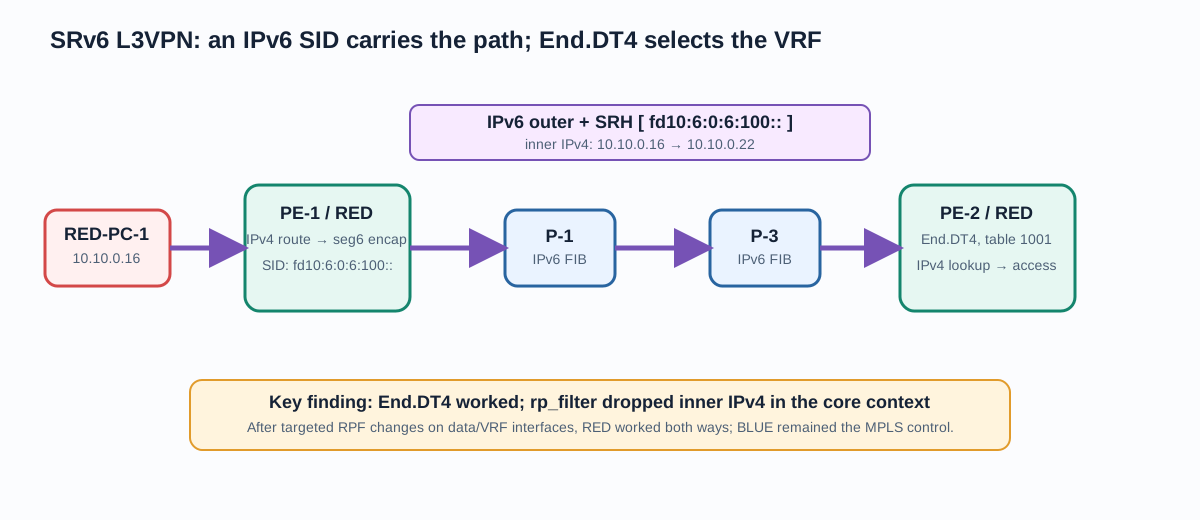
We then made the fix persistent with lab-srv6-red.service on PE-1 and PE-2. After networking, VRFs, and FRR were ready, the units idempotently restored the RPF settings, locator rule, egress End.DT4, IPv6 route to the peer SID, and IPv4 SRv6 encapsulation route. After restarting the services:
PE-1, RED table 1001
10.10.0.22/31 encap seg6 mode encap segs [fd10:6:0:6:100::] dev ens4

PE-2, RED table 1001
10.10.0.16/31 encap seg6 mode encap segs [fd10:6:0:11:100::] dev ens4

RED-PC-1 → RED-PC-2: 3/3 replies, 0% loss
RED-PC-2 → RED-PC-1: 3/3 replies, 0% loss
The core saw SRHs with the correct inner IPv4 traffic in both directions. BLUE was deliberately left unmigrated: it remained the control MPLS L3VPN with encap mpls 16004/16006/81 and continued to ping successfully. That is a particularly satisfying result: one topology now demonstrates two working ways to carry the same kind of service.
What We Actually Built
This was not “a configuration in nine chapters,” but a set of proven layers:
- Every P2P link has IPv4 connectivity, adjacent addresses are reachable, and forwarding is enabled only where required.
- OSPFv2 carries PE loopbacks; the route is confirmed by FRR, the Linux FIB, and an actual ping.
- LDP distributes labels, and a packet capture shows MPLS in transit.
- RED and BLUE are isolated through VRFs and RTs; MPLS L3VPN carries a transport label plus a service label, while cross-service traffic correctly fails.
- OSPF TE distributes TE LSAs, but is not falsely advertised as RSVP-TE on an FRR build without
rsvpd. - SR-MPLS Node SIDs work in the FIB, and an SR policy really steers RED through P-1 → P-3 → PE-2.
- RED is a working static SRv6 L3VPN data plane: the SRH crosses the core,
End.DT4delivers IPv4 into the correct VRF, and traffic works in both directions.
That last qualifier matters. This is not yet a native BGP SRv6 L3VPN control plane. Local systemd scripts restore the RED SIDs and service routes. The next sensible layer would be advertisement and steering through a supported BGP SRv6 control plane. That step is worth attempting precisely because the data plane is already proven. Now there is something real to put a control plane on top of, instead of doing it the other way around.
Further Reading
- RFC 8986: Segment Routing over IPv6 — the SID and behavior model.
- Linux seg6 sysctl — why Linux does not simply accept an SRH by default.
- Linux self-test for SRv6 End.DT4 L3VPN — a minimal reference model for the service data plane.
- FRR OSPF documentation — OSPF TE and the experimental SR-MPLS support in the branch used here.
- FRR pathd — SR Policy, candidate paths, and binding SIDs.
The next episode could add a controller, PCEP, or BGP SRv6 services. But then the problem would no longer be making the packet move at all. It would be deciding how to express intent—and that, as usual, is an entirely separate way to make a network interesting.